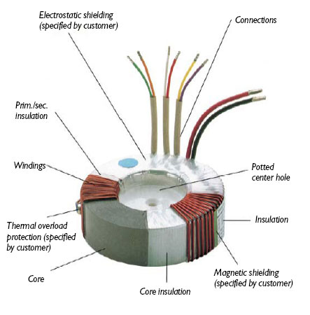
Toroidal Transformers - A Detail Analysis
In these days of shrinking package size, the transformer
is usually the largest component in a given circuit. The geometry of a standard
transformer limits how small we can make it as size is proportional to the square
root of the total transformer power. However, the familiar E-I core is not the
only one that can be used. For instance, using a toroidal, or donut-shaped core
makes it possible to reduce the size and weight of a transformer by 20% to 50%
compared with conventional cores with-out sacrificing performance. That's possible
because core losses in toroids are typically 10% to 20% of the total power loss,
with the balance being lost in the windings. That compares with core losses
totaling 50% of the total power loss for conventional transformers. Lower core
losses provide cooler operating temperatures and low magnetizing current. The
toroidal transformer design best uses the high permeability and low-loss characteristics
of a modern transformer core. Toroids are commonly used for current and instrument
transformers, where low losses are extremely important. Other advantages are
higher efficiency lower operating temperature, before regulation, and lower
noise. The disadvantage is somewhat higher cost, although improved production
techniques are making toroidal transformers more cost competitive.
The inherent advantages of the toroidal (ring,
donut shaped core) transformer, relative to other core configurations, may be
summarized generally as (1) nearly ideal magnetic circuit, which results in
(2) lower stray magnetic field, (3) less volume and weight, (4) less audible
hum, and (5) higher efficiency. Which benefits are of interest in a particular
application depend on the type of product and sensitivity of other circuitry
to stray magnetic field.
TOROID'S IDEAL MAGNETIC CIRCUIT
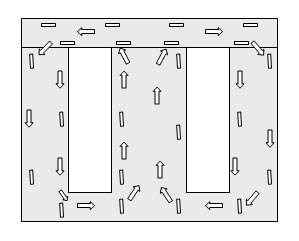
In an E-I structure it is difficult to align the
grain structure of the stamped laminations with the flux path over the entire
magnetic path. This inability leads to higher core loss and less efficient operation
when compared to toroids. Figure 1 shows a comparison of grain alignment with
flux path for a toroidal and E-I laminate.
FIGURE 1
LOW STRAY FIELD
Common laminated transformer designs employ a
bobbin wound coil placed over a stack of "E" shaped laminations. An
"I" shaped stack is butted to the "E", completing the magnetic
path. The connection between the E and I is never a perfect junction, giving
rise to a discontinuity, or air gap in the magnetic flux path. This gap, having
higher reluctance, causes greater radiated magnetic field. In any core with
a gap, the properties of the gap are unpredictable, and depend upon pressure
and the quality of the surfaces of the gap.
A second feature which gives rise to leakage flux in E-I core transformers is
the discontinuity in the windings that surround the flux path. The windings
are concentrated in short regions of the laminates, which leaves large portions
of the flux path exposed. The abrupt transition from windings to bare laminates
creates opportunity for the flux to escape the confinement of the core and form
linkage paths outside the transformer. The transitions in the windings can also
lead to high leakage inductances for the device.
There is no air gap in the toroidal transformer. The core is tightly wound onto
a mandrel, like a clock spring, from a continuous strip of grain oriented electrical
steel. Spot welding at the beginning and end prevents loosening. The stresses,
which could result in unacceptable core loss, introduced by derailing and winding
are relieved by annealing the wound core in a dry nitrogen atmosphere. The result
is a stable, predictable core, free from discontinuities, holes, clamps and
gaps.
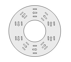
stray
FIELD AT 100 mm FROM CENTER
30 10 80 120 1i0 180 210 240 270 XX) 330
POLAR ORIENTATION OF TRANSFORMER (DEGREES)
Figure 2
REDUCED
WEIGHT AND SIZE
In the E-I structure, the magnetic flux is not
aligned with the grain of the steel for approximately 25 per cent of the flux
path (refer to Figure 1). This misalignment causes higher magnetization losses
and reduces the maximum flux density that can be utilized in the core. Higher
efficiencies have been made possible by using high grades of grain-oriented
steel, which increases flux densities while minimizing losses. However, maximum
utilization of these properties occurs only when the flux in the steel is parallel
to the grain direction. It can be seen in Figure 1 that the flux in a toroidal
core is 100% aligned with the grain of the steel. The typical working flux density
of EI laminates is from 1.2 to 1.4 Tesla, whereas toroids typically operate
from 1.6 to 1.8 Tesla.
For a given core cross section, the voltage induced
in a winding is directly proportional to the flux density and number of turns.
The higher allowable flux density of a toroid requires fewer turns of wire in
all windings to achieve the same result.
Comparison of a 960 VA E-I laminate of known characteristics with an equivalent
toroid shows the weight and volume of the toroid to be 50% that of the E-I laminate.
In an existing product which uses an E-I laminate, it is often possible to replace
the E-I with a toroid which has close to the same footprint, but is only 60
per cent as tall. In the case where it is desirable to increase the power supply
power rating without increasing its size, the E-I might be replaced with a toroid
which is the same size as the E-I, but has 1.5 to 2 times the power capability.
It is true that the empty center hole in a toroidal transformer, which is needed
to enable winding, occupies some wasted volume. This wasted volume deficit is
overcome by the toroid's volume advantage at roughly 50 VA and above. So, in
transformers rated less than 50 VA, reduced size is not a factor, but the other
advantages remain.
AUDIBLE
HUM
Audible hum in transformers is caused by vibration
of the windings and core layers due to forces between coil turns and core laminations.
Clamps, bands, rivets, and welds cannot bind the entire structure. Varnish penetrates
the laminations only partially. Laminations tend to loosen over time, producing
increasing hum. The nature of the toroidal transformer's construction helps
to dampen acoustic noise. The core is tightly wound in clock spring fashion,
spot welded, annealed and coated with epoxy resin.
Audible hum, heard immediately after application of power, may be noticeable
in the toroid, and then die down to a quieter level a few seconds after power
is applied. This is a result of the toroid's greater inrush current.
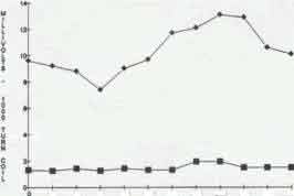
EFFICIENCY
Efficiency of a transformer is stated as:
Pout
Efficiency = ______________________
Pin
Where Pout is the useful output power delivered
to the load, and Pin is the power input to the transformer. The difference between
Pin and Pout is consumed by losses in the core and windings. The ideal magnetic
circuit of the toroid, and the ability to run at higher flux density than E-I
laminates, reduces the number of turns of wire required and/or the core cross
sectional area. Either benefit reduces the losses. Toroidal transformers typically
are 90 to 95 per cent efficient; whereas E-I laminates have a typical efficiency
of less than 90 per cent.
In recent years, more attention is being given
to energy efficiency of electrical equipment, and legislation has been considered
which would encourage minimum efficiency standards for all types of electrical
products, with lighting and computer equipment being the most prominent. The
toroidal transformer will serve as a method for achieving compliance to these
new energy efficiency standards.
A toroidal transformer does a better job of reducing
those losses to their minimum practical values than any other production core
form, so why not try to use one in your next project?
For more information, please send your inquiry to sales@eea-trafo.com